3D Modeling with Clarity and Precision for Physical Printing
ModelSteps3d produces step-by-step guides that demystify CAD geometry, slicer tolerances, and mechanical fit. Learn practical modeling workflows built specifically for reliable additive manufacturing.
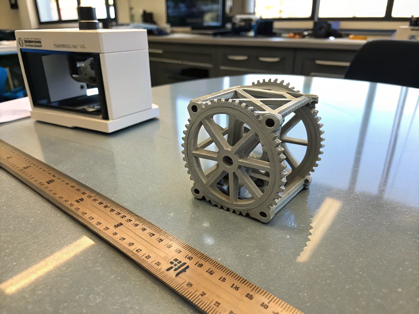
Geometric Parameters
VERIFIED REPRODUCIBLE0.12 – 0.20 mm
+-0.15 mm
STEP & STL
100% Manifold
All tutorial models are pre-tested on standard 0.4mm brass nozzles with PLA, PETG, and Resin profiles.
Built on Three Technical Pillars
Every step-by-step tutorial published by ModelSteps3d follows a strict craft methodology—ensuring your 3D models transition seamlessly from CAD screen to tangible, functional physical prints.
Every tutorial starts with watertight boundary representation, zero non-manifold edges, and clean wall thickness calculations designed specifically for additive manufacturing.
- Draft angle verification for clean layer stacking
- Stress distribution ribbing and chamfering
- Parametric dimensioning in CAD workspaces
Bridge the gap between digital geometry and physical machine physics with fine-tuned layer heights, seam placement strategy, and minimal support structure mechanics.
- Volumetric flow rate calibration guides
- Z-seam alignment along non-critical edges
- Organic tree support geometry tuning
Complete the build cycle with tactile post-processing, functional press-fit clearance testing, mechanical thread inserts, and surface refinement standards.
- Thermal brass insert seating procedures
- Multi-part interlocking key calibrations
- Sanding, priming, and coating workflows
Ready to explore our guided tutorials?
Follow comprehensive step-by-step documentation with downloadable source files and printer profiles.
The Step-by-Step Method
From initial parametric vector math to physical layer extrusion. Follow our four-stage framework designed for repeatable, production-grade 3D print results.
Methodology
ISO/ASTM 52900
Tolerance
±0.05 mm
Status
Reproducible
Parametric CAD Sketching
Constraint-driven geometry & mechanical tolerances
Mesh Topology & Wall Optimization
Manifold verification & per-perimeter reinforcement
Slicing & Toolpath Calibration
Layer height micro-stepping & extrusion cooling dynamics
Additive Production & Inspection
Physical extrusion, bed adhesion & vernier caliper audit
Every tutorial begins with solid geometry defined by exact dimensional constraints. We build editable sketch trees with variable clearance offsets tailored specifically for additive manufacturing physics.
Base Clearance
Chamfer Angle
Fillet Radius
Draft Taper
Quality Gate Checklist

Workshop Precision Standard
All steps in our guides are physically test-printed on standard 0.4mm nozzle FDM printers and 50μm SLA platforms to guarantee that every tolerance fits straight off the bed.
Submit a Geometric Challenge or Custom Tutorial Request
Have a tricky mechanical assembly, organic lattice structure, or complex print tolerance you need deconstructed? Tell us about your project requirements.
What each tutorial delivers
Manifold & Slice Verification
Every step is verified for zero non-manifold edges and physical printability.
Parametric Precision
Exact clearances, wall thickness tolerances, and support-free overhang logic.
Complete Open Assets
Step-by-step documentation paired with downloadable source CAD and STL files.